
Every thermal design starts the same way: take the dissipated power, find the allowable temperature rise, and size an aluminium heat sink to suit. For a large share of electronics — drives, supplies, controllers, LED fixtures — that is the whole story, and the engineering effort goes into choosing the right fin geometry and manufacturing route.
But two trends keep colliding: components dissipate more power from smaller footprints, and enclosures keep shrinking. Sooner or later a design arrives where the numbers refuse to work — not because there isn’t enough fin area, but because the heat cannot spread from a small, intense source into that area quickly enough. The base of the heat sink becomes the bottleneck. That is the problem heat pipes exist to solve.
What a heat pipe actually does
A heat pipe is a sealed tube — for electronics cooling, almost always a copper envelope with water as the working fluid — containing a wick structure and a small charge of fluid under partial vacuum. At the hot end the fluid evaporates; the vapour rushes to the cold end, condenses, and gives up its latent heat; the wick returns the condensate by capillary action. The cycle is passive, silent, and has no moving parts.
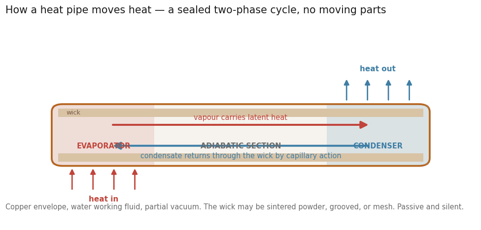
Because it moves heat as latent heat of vaporisation rather than by conduction, a heat pipe transports heat far more effectively than any solid metal of the same cross-section — its effective thermal conductivity is many times that of solid copper, with the exact figure depending strongly on length, orientation, wick structure and operating temperature. The practical consequence is simple: a heat pipe lets you pick heat up in one place and put it down somewhere better.
When a solid heat sink is still the right answer
Heat pipes earn their place only when spreading or distance is the limiting factor. If the heat source is reasonably large relative to the sink base, if the fins can sit directly above the source, and if the thermal budget closes with a sensible extrusion, the solid heat sink wins on every other axis: it is cheaper, lighter on assembly labour, immune to orientation effects, and has nothing inside it to fail or degrade. A well-chosen extruded profile, correctly mounted, is still the backbone of electronics cooling — and adding heat pipes to a design that doesn’t need them adds cost and failure modes for no thermal return.
A practical rule of thumb: exhaust the conventional options first — a thicker base, a copper slug under the hot spot, a better interface material, more airflow. When those stop paying, you are in heat-pipe territory. Our earlier note on heat sink optimisation and thermal design covers the ground you should clear before reaching for two-phase cooling.
The three jobs heat pipes do in an assembly
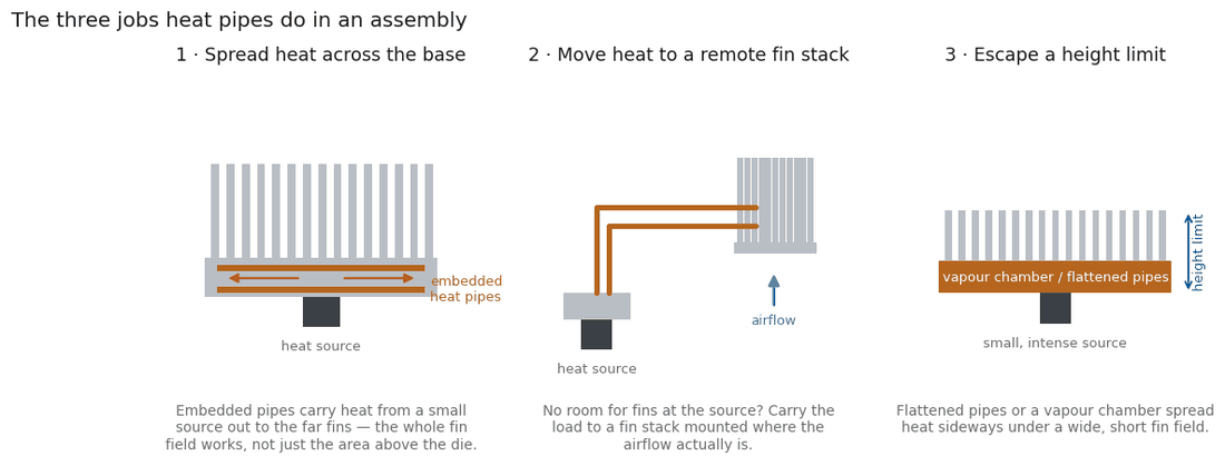
Spreading heat across a base. Heat pipes flattened and embedded into machined grooves in a heat-sink base carry heat from a concentrated source out to the far fins, making the whole fin field work instead of just the region above the die. This is the most common upgrade path when an existing extruded sink underperforms: same envelope, same footprint, dramatically better utilisation.
Moving heat to a remote fin stack. When there is simply no room for fins near the source — sealed enclosures, dense boards, display panels — heat pipes carry the load to a fin stack mounted where the airflow actually is. The fin stack itself is usually a zipper-fin or bonded assembly, sized independently of the source location.
Escaping height limits. Low-profile designs that cannot accommodate a tall sink can use flattened heat pipes or a vapour chamber to spread heat laterally under a wide, short fin field. A vapour chamber is conceptually a heat pipe in plate form — the same two-phase cycle, spread over an area — and competes with embedded-pipe designs when the source is very small and the base is wide.
Design considerations that decide performance
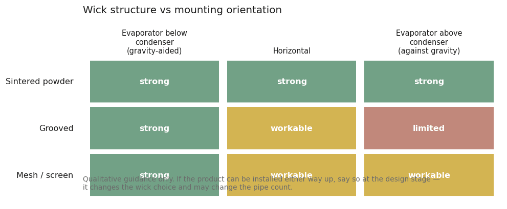
Orientation and gravity. The wick returns fluid against gravity only up to a point. A heat pipe working with gravity (evaporator below condenser) performs best; one working against it depends entirely on wick capillary performance. If the equipment’s mounting orientation is undefined — or the product can be installed either way up — say so at the design stage, because it changes the wick choice and may change the pipe count.
Bending and flattening. Routing a pipe around a board or flattening it into a thin base both reduce its capacity — every bend and every reduction in cross-section costs something. The design rule is to keep bends as few and as gentle as the envelope allows, and to let the thermal designer know the routing constraints early rather than bending the pipe to fit at the end.
Wick structure. Sintered-powder wicks handle against-gravity operation and fine capillary demands; grooved wicks excel in gravity-aligned, straight runs; mesh wicks sit between. The choice is an engineering decision driven by orientation, power and geometry — one reason a heat-pipe assembly should be specified by its required performance, not by copying a pipe count from a similar-looking product.
Attachment and interfaces. Every joint between pipe and base, and pipe and fin stack, adds thermal resistance. Soldered joints outperform epoxy; direct-contact designs — where the flattened pipe itself touches the component — remove an interface entirely. The mounting pressure and interface material at the component remain as important as they are for any solid sink.
From concept to fabricated assembly
A production heat-pipe assembly is a genuinely multi-process product: extruded or machined aluminium bases, grooving or drilling for the pipes, the pipes themselves with their wick and charge, stacked or bonded fins, soldering or epoxy assembly, and finally machining of mounting surfaces after assembly so that flatness at the component interface survives the joining steps. Surface treatment — typically anodising for the aluminium parts — comes last, with masking where electrical or thermal contact must be preserved.
That breadth is exactly why these assemblies are usually sourced rather than built up from catalogue parts: the thermal design, the fabrication tolerances and the assembly sequence have to be engineered together. PA International works across a vetted partner network covering custom heat pipe design and manufacturing, custom heat sink fabrication and aluminium extrusion, so a thermal problem can be taken from a datasheet power budget to a tested, volume-manufactured assembly — with the design choices above made deliberately, not by default.
If you have a design that has outgrown its heat sink — or a new one where the numbers won’t close — send us the thermal budget and the envelope. It is usually a short conversation to establish whether heat pipes belong in the answer.